

A combinational circuit is a digital logic system where the output is determined solely by the current state of input variables at any given instant. Unlike sequential systems, these circuits possess no memory elements, feedback loops, or clock signals. They utilize interconnected logic gates to perform specific arithmetic, data transmission, or code conversion functions immediately upon input application.
If you are preparing to attempt GATE 2026, understanding the behavior of a combinational circuit is non-negotiable. It is the bedrock of digital design.
Core Characteristics of Combinational Logic Systems
Combinational circuits define the backbone of digital electronics. They are characterized by their time-independent output behavior and lack of internal state retention. In simple terms? What you put in is immediately what gets processed, no waiting, no memory.
Any standard combinational circuit consists of:
- $n$ Input Variables
- $m$ Output Lines
- Boolean Functions: The strict logic defining the relationship between inputs and outputs.
Since the system does not depend on previous inputs, the combinational circuit analysis is straightforward: for every unique input combination, there is exactly one defined output combination. This property makes them faster and less complex than sequential circuits. However, they are susceptible to “glitches” (hazards) due to the varying propagation delays of logic gates.
Exam Tip: To identify a combinational circuit in a schematic, look for the absence of memory elements like flip-flops or latches.
Common Examples:
- Adders & Subtractors
- Multiplexers (MUX)
- Decoders & Encoders
Mastering Logic Circuit Analysis and Boolean Algebra
Logic circuit analysis involves breaking down complex diagrams into fundamental boolean expressions to predict output behavior using truth tables and logic gates.
To analyze a combinational circuit effectively, you must be proficient with logic gates (AND, OR, NOT, NAND, NOR, XOR, XNOR). The process typically begins by labeling all intermediate gate outputs and writing their Boolean expressions.
Quick Verification Guide
| Tool | Function | Exam Use Case |
| Boolean Algebra | Deriving equations | Simplifying complex logic manually. |
| Truth Tables | Mapping Inputs to Outputs | Verifying the final circuit function. |
| Universal Gates | NAND / NOR Implementation | Reducing gate count in fabrication. |
In 2026 exam patterns, questions often present a complex schematic and ask for the simplified boolean expression. Mastery of De Morgan’s laws allows for rapid combinational circuit simplification, saving you precious minutes.
Efficient Circuit Simplification Using Karnaugh Maps
Karnaugh Maps (K-maps) provide a graphical method to minimize Boolean expressions without the tedious algebraic manipulation required by standard Boolean algebra.
For any combinational circuit design, efficiency is paramount. A raw logic design derived directly from a truth table often contains redundant gates. The K-map technique organizes truth table data into a grid where adjacent cells differ by only one bit.
How to Optimize K-Maps for Exams:
- Group Large: Focus on grouping the largest possible power-of-two blocks (pairs, quads, or octets).
- Don’t Forget Don’t Cares: Use ‘X’ terms to increase group size.
- SOP vs POS: Group 1s for Sum of Products; Group 0s for Product of Sums.
Failing to simplify a combinational circuit leads to increased power consumption and propagation delay a big “no” in modern VLSI design.
Design Procedures for Arithmetic Combinational Circuits
Arithmetic circuits like adders and subtractors are the computational engines of a processor. These combinational circuits are designed by systematically mapping binary arithmetic rules to logic gate connections.
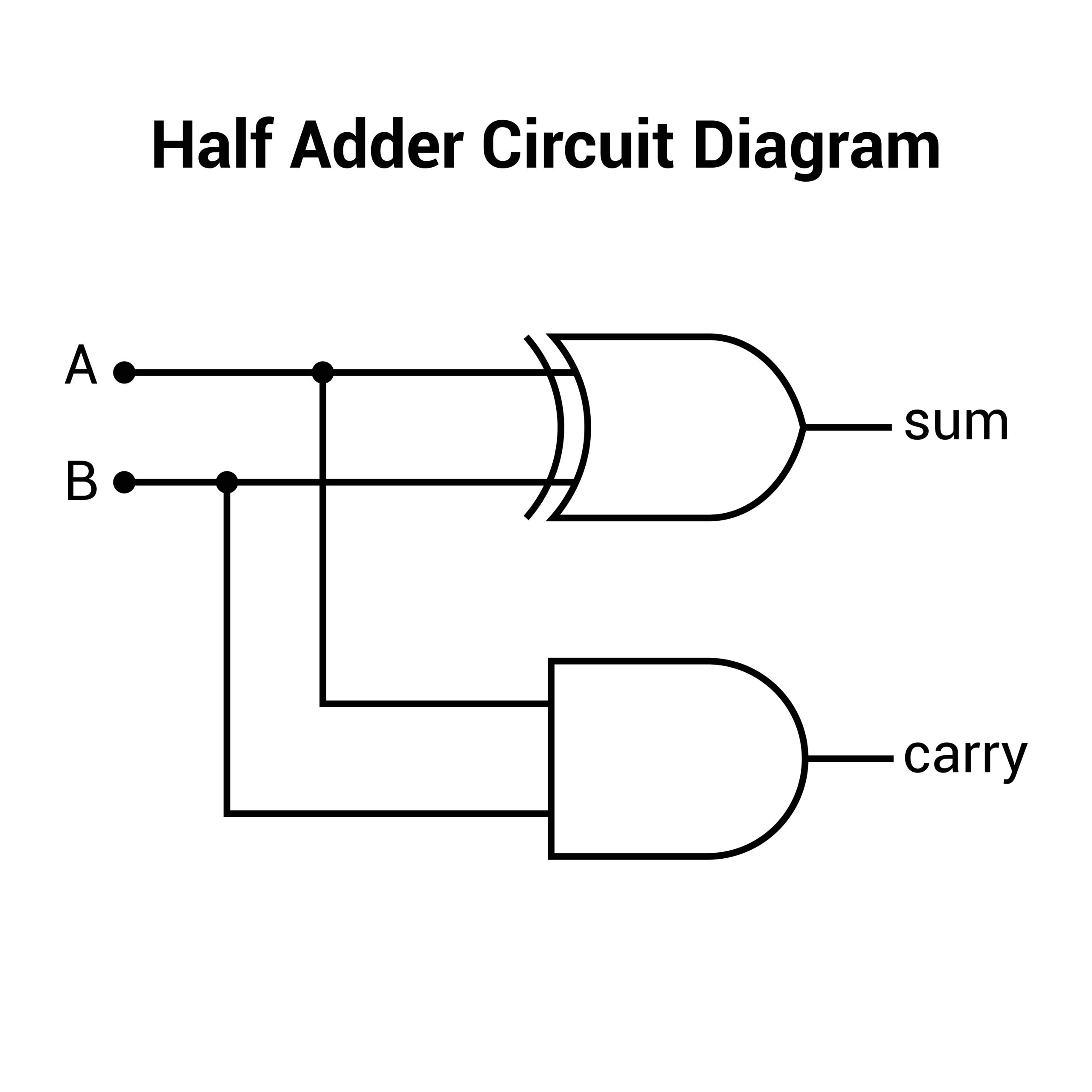
Half Adder vs. Full Adder
| Feature | Half Adder | Full Adder |
| Inputs | 2 (A, B) | 3 (A, B, Carry-in) |
| Outputs | Sum, Carry | Sum, Carry-out |
| Equation (Sum) | $A \oplus B$ | $A \oplus B \oplus C_{in}$ |
| Use Case | LSB Addition | Multi-bit Cascading |
For exams, simply memorizing the combinational circuit is insufficient. You must understand limitations, such as the propagation delay in Ripple Carry Adders. Just as you memorize the Circular Motion Formula for physics, you must memorize the carry propagation formulas for digital logic.
Data Transmission with Multiplexers and De-Multiplexers
Multiplexers (MUX) and De-Multiplexers (DEMUX) are critical combinational circuits used for routing data.
A Multiplexer, often called a “data selector,” routes one of $2^n$ inputs to a single output based on selection lines. In exams, the MUX is frequently termed a “Universal Logic Circuit” because any Boolean function can be implemented using a MUX without needing individual logic gates.
Quick Comparison:
- MUX (Many-to-One): Acts as a digital switch. Ideal for implementing boolean functions in objective questions.
- DEMUX (One-to-Many): Distributes a single input to multiple destinations. Fundamental for memory addressing.
Signal Conversion: Encoders and Priority Encoders
Encoders convert active data signals into a coded binary output. However, standard encoders fail if multiple inputs are high simultaneously.
The Solution: Priority Encoder
In a Priority Encoder, if two inputs are active, the output corresponds to the input with the highest designated priority. This combinational circuit is a staple in microprocessor interrupt handling.
- Real-World Scenario: If you are trying to Prepare GATE along with College, you have to prioritize tasks. Similarly, the CPU uses a Priority Encoder to decide which hardware interrupt to service first.
Practical Logic Circuit Analysis with Verilog Examples
Modern combinational circuit design rarely happens on paper; it occurs in code. Verilog HDL allows engineers to simulate and synthesize logic textually.
For exams covering VLSI, recognizing Verilog syntax is key. A combinational circuit is typically modeled using assign statements (dataflow) or always blocks (behavioral).
Example: 2:1 Multiplexer in Verilog
Verilog
// Concise Conditional Operator
assign out = (sel) ? b : a;
Understanding these combinational circuit examples bridges the gap between theoretical Boolean algebra and physical chip implementation.
Critical Perspective: Hazards in Combinational Logic
While combinational circuits theoretically produce instant outputs, real-world physics intervenes. Physical delays can cause temporary glitches known as hazards.
- Static Hazard: When the output momentarily flips to the wrong state due to unequal propagation delays.
- The Fix: Detect these using K-maps by finding adjacent groups not covered by a redundant loop and adding “hazard-covering” terms.
This depth of understanding distinguishes top-tier engineers. For more on standard engineering curriculums and syllabus updates, you can check the official NPTEL website.
Real-World Application: Arithmetic Logic Unit (ALU)
The Arithmetic Logic Unit (ALU) serves as the ultimate example of complex combinational logic. It integrates multiplexers, adders, and logic gates to execute CPU instructions.
The ALU does not store data; it processes it. It consists of a bank of function units feeding into a large Multiplexer. Practical logic analysis of an ALU reveals the importance of modular design—reusing a single 1-bit ALU block to create a 32-bit system.
Exam Shortcuts and Problem-Solving Strategies
Success in 2026 competitive exams requires rapid pattern recognition. Here are your shortcuts for combinational circuit problems:
- MUX Implementation: Don’t draw the whole table. Group minterms in pairs. The relation to the third variable becomes your data input.
- Decoder Logic: A Decoder with active-high outputs generates Minterms. Just OR the relevant outputs.
- Speed Checks: For questions on adder speed, “Carry Look-Ahead” is almost always the correct answer for high-speed requirements.
- Universal Gates: If a circuit uses only NAND/NOR, cancel out double inversion bubbles to see the true logic instantly.
By applying these strategies to combinational circuit design, you reduce calculation time and eliminate silly errors.
Learn More
- GATE Study Notes 2026
- BSNL JTO Salary in 2026
- Chemical Engineering Salary in india
- Biomedical Engineer salary in india
- GATE Study Material 2026
Frequently Asked Questions (FAQs)
Why is Boolean algebra essential for logic circuit analysis?
Boolean algebra provides the mathematical framework to describe and simplify the behavior of logic gates. Using its laws, such as De Morgan’s Theorem, you can reduce complex circuits into their simplest forms to minimize hardware requirements.
How to use a Karnaugh Map for circuit simplification?
To use a K-map, transfer truth table outputs into the grid and group adjacent 1s (for SOP) or 0s (for POS) in powers of two. These groupings allow you to visually identify and eliminate redundant variables in a combinational circuit design.
Why this preference for Carry Look-Ahead Adders over Ripple Carry Adders?
Ripple Carry Adders suffer from high propagation delays because each stage must wait for the previous carry. Carry Look-Ahead Adders calculate carry signals in parallel, making them significantly faster for high-speed computational tasks in exams.
How to implement any Boolean function using a Multiplexer?
A Multiplexer acts as a universal logic circuit. By connecting the function variables to the selection lines and the appropriate logic constants (0, 1, or the remaining variable) to the data inputs, you can replicate any truth table without extra gates.
Why this distinction between a standard Encoder and a Priority Encoder?
Standard encoders produce errors if multiple inputs are active at once. A Priority Encoder resolves this conflict by only processing the input with the highest designated priority, which is critical for system interrupt handling.
How to detect and fix static hazards in a combinational circuit?
Hazards are detected by finding adjacent 1s in a K-map that are not covered by the same product term. You can fix them by adding a redundant "cover" term to the Boolean expression, ensuring a smooth transition between input changes.